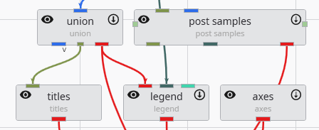
The Application Network is the primary workspace in Earth Volumetric Studio for building and managing your data processing workflows. It is a visual, node-based environment where you construct “applications” by placing modules and connecting them to define a data flow from input to final visualization.
Modules
Modules are the fundamental building blocks of an application. Each module performs a specific task, such as reading data, performing a calculation, creating a geometric object, or rendering a scene. They are represented by rectangles on the Application Network, each stating a user-defined name and the module type under it. You add modules to your network by dragging them from the Module Library onto the Application Network canvas.
Each module has a set of icons that appear when you hover over it, providing quick access to key functions:
| Icon | Description |
|---|---|
| Disable/Enable Module | Clicking this icon disables the module and any downstream modules that depend on it. A disabled module will not execute when the application is run. The icon appearance will change to quickly notice disabled modules. Clicking the icon again re-enables it and will make it run immediately. |
| Hide/Show Output | This icon is available on modules that produce a visual output. Clicking the eye icon toggles the visibility of that module’s output in all viewers. |
See Module Icons for more information.
Ports and Connections
Modules communicate with each other through ports. Each module has one or more input ports (on the top) and output ports (on the bottom). You create Connections between modules which define the top-down Data Flow of the application, directing the output of one module to become the input for the next. See the Connecting and Disconnecting Modules topic.
Ports are color-coded to indicate the type of data they handle, and you can only connect ports of a similar color. While there are many port types, the two most critical and frequently used are Field ports and Renderable Object ports.
See Port Colors, Red Port Properties (Renderable Port) and Blue Port Properties (Field Port) for more information about ports.
How to Remove connections
Connections can be removed by selecting the connection with the left mouse button in the Application Network and then either using the DEL key or by clicking the right mouse button and choosing the Disconnect option.
Module Right-Click Menu
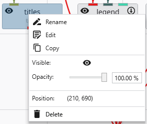
Right-clicking on any module in the Application Network opens a context menu that provides quick access to several common actions and properties for that module.
| Option | Description |
|---|---|
| Rename | Allows you to change the display name of the module as it appears on the Application Network canvas. |
| Edit | Opens the selected module’s parameters in the Properties window. |
| Copy | Creates a duplicate of the selected module, including its current settings. The new module can be pasted with CTRL+V. |
| Visible | This toggle, represented by an eye icon, controls the visibility of the module’s output in the viewer (applies only to modules with a red output port). |
| Opacity | This slider and input box allow you to adjust the transparency of the module’s visual output in the viewer. |
| Position | Displays the read-only X and Y coordinates of the module’s top-left corner on the Application Network canvas. |
| Delete | Removes the module and all of its connections from the Application Network. |
Input Port Context Menu
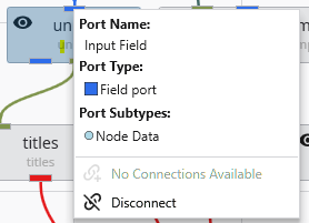
Right-clicking on a module’s input port opens a context menu providing details and actions for the incoming connection.
| Option | Description |
|---|---|
| Port Name | Displays the name of the port. |
| Port Type | Shows the type of data the port accepts, indicated by a colored icon and a description. |
| Port Subtypes | Lists the specific kinds of data this port requires the output port to provide. |
| No Connections Available / Connect from… | Indicates if compatible output ports are available. If so, it allows you to create a connection. |
| Disconnect | Removes the connection that is currently feeding data into this port. See Connecting and Disconnecting Modules. |
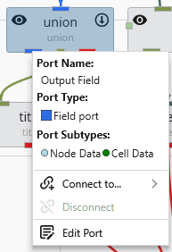
Output Port Context Menu
Right-clicking on a module’s output port opens a context menu with information and actions related to that specific port.
| Option | Description |
|---|---|
| Port Name | Displays the name of the port. |
| Port Type | Shows the type of data the port provides, indicated by a colored icon and a description. |
| Port Subtypes | Lists the specific kinds of data this port provides, such as “Node Data” or “Cell Data”. |
| Connect to… | Opens a submenu listing all compatible input ports on other modules in the network to create a new connection. |
| Disconnect | Removes an existing connection originating from this port. See Connecting and Disconnecting Modules. |
| Edit Port | Opens the options for the port in the Properties window for more advanced configuration. |
Modules in the Application Network feature a set of icons directly on their surface that provide at-a-glance information and quick control over their execution and visibility. Modules that can be executed or produce a visible output have icons on their left and right sides. The right-side icon controls execution, while the left-side icon controls visibility in the viewer.
Modules in the Application Network display several visual cues to indicate their current status. These indicators help you quickly understand which module is selected, which is being edited, whether a module has run successfully, and if it is set to execute automatically. This allows for efficient management of your application’s workflow. Selection and Editing Status The border of a module changes color to reflect its selection and editing state.
Connecting and Disconnecting Modules
Modules in the Application Network are linked together by connections, which represent the flow of data from an output port of one module to an input port of another. Creating and removing these connections is fundamental to building and modifying your application’s workflow. The system helps ensure that you only make valid connections between compatible port types.
The color of the ports on a module provides an immediate visual cue about the type of data they accept or output. Understanding these colors and types helps in quickly assessing a module’s function and ensuring you are making valid connections within the Application Network. Port Types Each port type is designed to handle a specific kind of data. The primary types are listed below.