cross section tubes
The cross section tubes module is used to produce open or closed tubes of user defined cross-section and constant or data dependent radius using 3D lines or polylines as input for the centerline and a single 2D polyline as the cross-section of the tubes.
Rotation of the cross-section is done with the Phase slider (or type-in), which is specified in degrees. There are two methods used to maintain continuity of the tube orientation as the path meanders along a 3D path. These are specified as the Phase Determination method:
- Force Z Up: is the default and is most appropriate for paths that stay relatively horizontal. This option keeps the tube cross-section aligned with the Z axis and therefore with a slope of 30 degrees, the effective cross sectional area of the tube would be reduced by cos(30) which would be a 14% reduction. However for the typical slopes found with tunneling this effect is quite minimal and this option keeps the tube perfectly aligned.
- Perpendicular Extrusions: keeps the tube cross-section aligned with the tube (extrusion) path and therefore preserves the cross-section no matter what the path. However, cross-section rotation creep is possible.
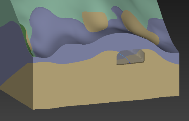
The cross section field input must be a closed polyline that is drawn in the X-Y plane in the correct size. It should be balanced about the origin in X, usually with the Y axis (X=0) at the floor of the tunnel. This results in the tunnel being created such that the tunnel path will be at the centerline FLOOR of the tunnel as shown in the picture below.
Ports
| Direction | Name | Type | Description |
|---|---|---|---|
| Input | Input Field | Field | A field of lines to be used in the creation of tubes. |
| Input | Input Cross Section Field | Field | A field of lines to be used as the cross section of the tubes. |
| Output | Output Field | Field | The tubes field. |
| Output | Output Object | Renderable | A renderable object to display. |
Properties
| Property | Type | Description |
|---|---|---|
| Allow Run | Boolean | Controls whether the module is allowed to execute. |
| Radius By | Choice: Constant, Cell Data Component, Node Data Component | The Radius By choice allows the user to choose constant or data dependent radius scaling. |
| Constant Data For Radius | Double | If Radius By is set to Constant, the Constant Data For Radius can be set using this control. |
| Cell Data For Radius | Choice | The Cell Data for Radius allows you to choose the cell data component for scaling. |
| Nodal Data For Radius | Choice | The Nodal Data for Radius allows you to choose the nodal data component for scaling. |
| Scale Factor | Double | The Scale Factor value is multiplied by the nodal data to determine the radius. |
| Minimum Radius | Double | The Minimum Radius control sets the minimum tube radius. |
| Tolerance | Double | The Tolerance parameter determines the maximum distance between nodes of adjacent line segments before those lines’ nodes should be merged to form a polyline. This also applies to closed polyline contours. Closed polylines will have their starting and ending nodes merged to form closed (toroidal) annuli. |
| Close Tubes | Boolean | The Close Tubes toggle causes the tubes to have solid ends. However the tubes are not solid objects (they are hollow). |
| Connect Tubes | Boolean | If the Connect Tubes toggle is on, tubes formed by connecting line segments will connect together. |
| Percentile | Double | The Percentile value allows you to control the automatic scaling of tubes based on the nth percentile value (versus the maximum 100th%). This addresses datasets where there are only a few nodes with extremely high values. |
| Phase | Double | The Phase value allows you to control the apparent rotation of tubes. This is specified in degrees of rotation. |
| Phase Determination | Choice: Perpendicular Extrusion, Force Z Up | The Phase Determination is used to set how the tubes are aligned. Perpendicular Extrusion is typically preferred if tubes approach vertical. Force Z Up works better for horizontal tubes. |
Data Output
| Property | Type | Description |
|---|---|---|
| Map Nodal Data | Multi-select | The Map Nodal Data options allow the user to select those nodal data components that are used for coloring or subsequent subsetting operations. |
| Map Cell Data | Multi-select | The Map Cell Data options allow the user to select those cell data components that are used for coloring or subsequent subsetting operations. |
| Include Center Data | Boolean | The Include Center Data toggle will tell the module to include the center point of each tube end point as a cell data component. This allows the user to probe onto the tube and return its center instead of the position on the outside of the tube. |