APDV files represent analyte data which is measured at points. The data can be collected at scattered locations or along borings. When boring IDs are included in the file, post samples will draw the borings as well as the samples.
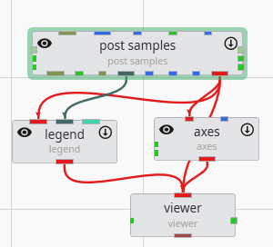
Create the following application. It is nearly identical to the application used for PGF files, but we do not need to connect the yellow port which contains geology or lithology names, as those are not applicable to APDV (or AIDV) files. However, if you do connect it, it won’t hurt anything.
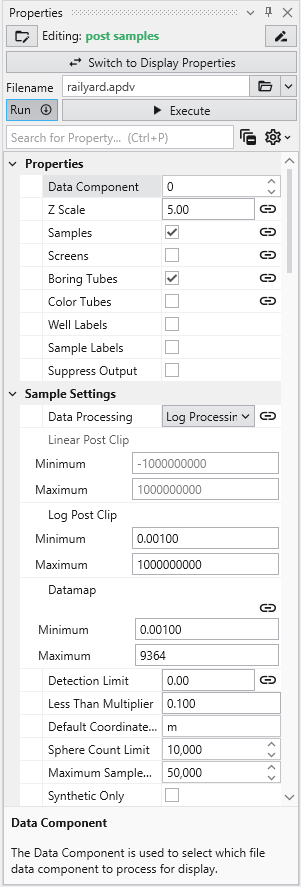
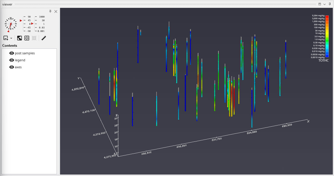
Double click on post samples to open its Properties window. Select Analytic and Stratigraphic Modeling\railyard.apdv and change the Z Scale to 5 on the Application window or Application Properties.
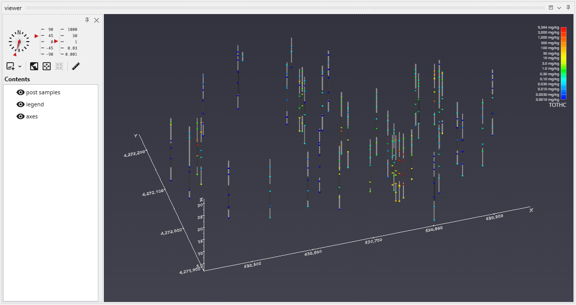
to show the following in the viewer.
post samples has many options for displaying this type of data (also applicable to PGF, GEO, AIDV). These include (but are not limited to):
- displaying the data as colored tubes (with or without spheres/glyphs)
- using different glyphs to represent each sample (a sphere is the default glyph)
- changing the diameter of glyphs or tubes based on the data magnitudes
- labeling the samples and/or borings
Let’s see the four options above:
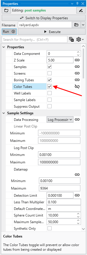
It is easy to display colored tubes. You can scroll down to the Color Tubesoption in the “Properties” cagtegory.
Check the Color Tubes option:
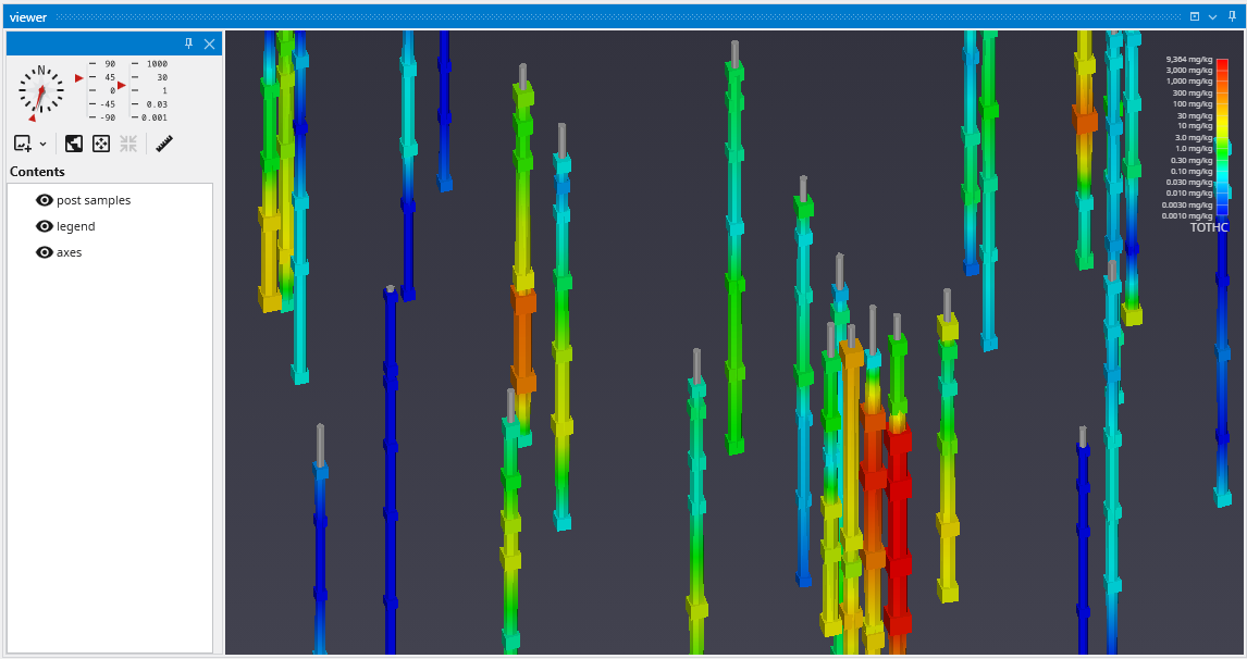
To change glyphs is incredibly simple. We just go to the Glyph Settings, and we’ll change the Generated Glyph to be Cube instead of the default Sphere, and we’ll also set the Maximum Scale Factor to be 200%
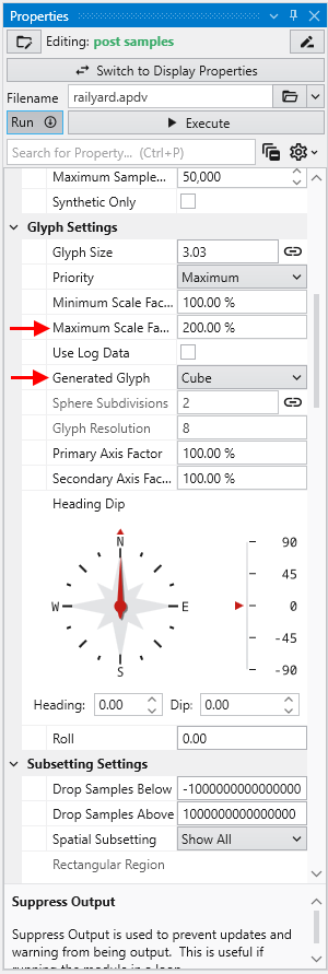
Since we’ve still left colored tubes on, our viewer shows:
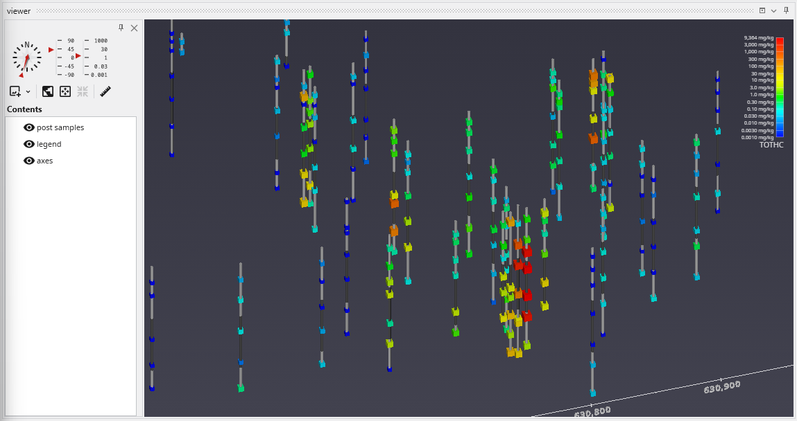
Before we make any other changes let’s uncheck the Color Tubes option again which will change our view to be:
Finally, we’ll add labels at each sample and the top of the borings:
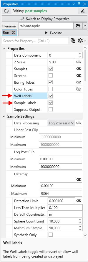
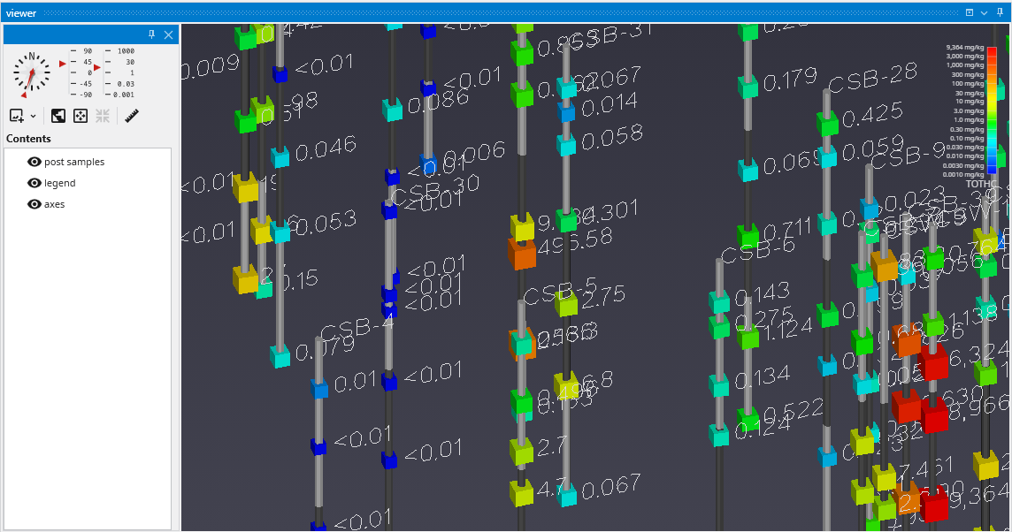
When working with dense datasets, sample labels can become cluttered and difficult to read. The post samples module includes label subsetting features to resolve this by intelligently blanking labels to improve clarity. This functionality is controlled by the Label Subsetting option in the Label Settings category.
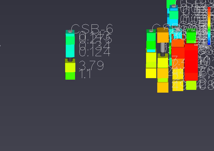
For example, if you set the Z Scale in the Application Properties to 1.0 and zoom in on a boring with dense data, such as CBS-6, you will see the problem of overlapping and unreadable labels:
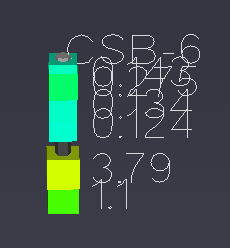
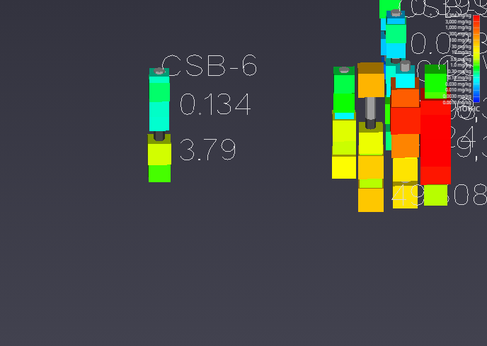
To resolve this, locate the Label Subsetting option and set it to Blank Labels.
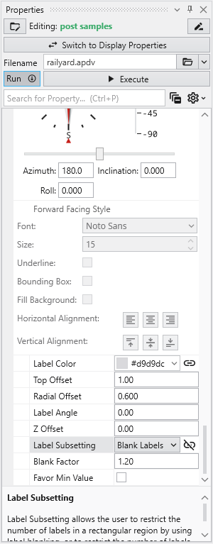
By default, Label Subsetting is set to None. Changing it to Blank Labels enables collision detection, which hides lower-priority labels that overlap with higher-priority ones. Label priority is determined by the sample’s value, with higher values taking precedence. Well labels, if enabled, are always given the highest priority. The result is a much cleaner and more informative visualization.
| Before: No Blanking | After: Blanking Enabled |
|---|---|
| 
|
You can further refine the display using the following settings:
- Blanking Factor: This setting controls the size of the buffer around each label used for collision detection. Increasing this value creates more space around labels, potentially blanking more of them.
- Boring Min/Max: This mode displays only one sample label per boring, either the one with the highest or lowest value. The Favor Min Value toggle determines which is shown.