cross_section_tubes
The cross_section_tubes module is used to produce open or closed tubes of user defined cross-section and constant or data dependent radius using 3D lines or polylines as input for the centerline and a single 2D polyline as the cross-section of the tubes.
Module Input Ports
- Input Field [Field] Accepts a field with or without data containing lines which represent the paths of the tubes.
- Input Cross Section Field [Field] Accepts a field which has the cross-section of the tubes.
Rotation of the cross-section is done with the Phase slider (or type-in), which is specified in degrees. There are two methods used to maintain continuity of the tube orientation as the path meanders along a 3D path. These are specified as the Phase Determination method:
- Force Z Up: is the default and is most appropriate for paths that stay relatively horizontal. This option keeps the tube cross-section aligned with the Z axis and therefore with a slope of 30 degrees, the effective cross sectional area of the tube would be reduced by cos(30) which would be a 14% reduction. However for the typical slopes found with tunneling this effect is quite minimal and this option keeps the tube perfectly aligned.
- Perpendicular Extrusions: keeps the tube cross-section aligned with the tube (extrusion) path and therefore preserves the cross-section no matter what the path. However, cross-section rotation creep is possible.
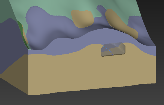
The cross section field input must be a closed polyline that is drawn in the X-Y plane in the correct size. It should be balanced about the origin in X, usually with the Y axis (X=0) at the floor of the tunnel. This results in the tunnel being created such that the tunnel path will be at the centerline FLOOR of the tunnel as shown in the picture below.
This tube was created with an EVS Line File (.elf) that was very simple and is shown below:
LINE
-10 0 0
-10 7 0
-7 10 0
7 10 0
10 7 0
10 0 0
CLOSE
END
As you can see, all of the Z coordinates are zero since they are irrelevant. This shape is balanced about the Y axis and is all Y >= 0
Module Output Ports
- Output Field [Field] Outputs the subsetted field as faces.
- Output Object [Renderable]: Outputs to the viewer.