For our next article in the “Tips and Tricks” section, I thought I would discuss another frequently asked question –
How do you place isolines on the top surface of a model?
As many of you know, this is quite straightforward if you are using the standard kriging modules in EVS to build your model. However, it can get tricky if the model is already created. This can happen if you are trying to use an old EVS Field File of a model that was generated in the past, or if you are bringing in the results of a groundwater modeling simulation. Fortunately, there is a way to accomplish this…
As I mentioned, if you are using the standard kriging modules, this is fairly straightforward. Just add a geologic_surface module to your network, and connect it to isolines.

The geologic_surface module provides elevation data directly for isolines, and allows you to pick any of the surfaces of the model.
But what happens when we start using a model coming from somewhere else? Let’s look at this same network, but this time, we’ll use an EFB (EVS Field File) that was saved previously…

There’s no Krig_3D_Geology anymore, which means we have no surface to connect to isolines!
If we still had the original geology file, we could add a Krig_3D_Geology to our network, and set it up to run the way we did before, but that would be a lot of extra information, and also adds an element of risk – it may be difficult (if not impossible) to exactly match the information that was used when creating the EFB file.
To make matters worse, this EFB file may have come from some other source – like the results of a groundwater model package. In that case, we may have never had a geology file that we can use.
Fortunately, there is a way to get there – the slope_aspect_splitter module.
This module was added in Version 8.5, and has many uses. In this case, it will let us take a 3D model and split off just the top surface of the model.
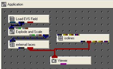
First, we’ll need to get a second Explode_and_Scale module. We’ll connect the green-gray and gray-brown ports from the main Explode_and_Scale module to our second, but in Explode_and_Scale#1, we’ll turn off all of the layers except the first. This Explode_and_Scale will now output a copy of just the first layer of our model. Without this, we would get isolines on the tops of each layer – not just on our top surface of the model.
We’ll pass Explode_and_Scale#1 into our new slope_aspect_splitter module, then connect it’s first blue-black port to our isolines. Our network now looks like this:

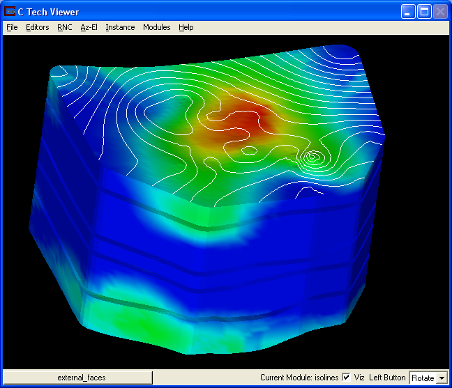
Once you have this connected, you’ll see isolines. By going into isolines and choosing Elevation as my Iso Component, and setting the min and max values appropriately, I was able to create the following picture:

In this case, everything worked with all the default settings for slope_aspect_splitter. This module is the one that does all of the difficult work for us. Let’s look at its user interface:

This module works by taking all of the external surfaces of a model, and splitting them into two separate outputs for us based on the slope or aspect of individual triangles in the model. By default, any surfaces with a slope of less than 89.9 (everything facing upwards) are output in the first blue-black port, and any surfaces with a slope greater than 90 degrees (facing sideways or down) are output to the second blue-black port.
The slope_aspect_splitter module lets us use the standard math routines in EVS to customize this, so we could do things like texture just the north facing walls of a building with texture_walls, or put a texture_map on just the upper surface of a model, or anything else that can be determined by slope or aspect.
In this case, it allowed us to separate out just the top surface of our model, and use it for isolines, without having the original input data.
