The C Tech 3D PDF Converter creates interactive 3D PDF documents from EVSPDF files exported from Earth Volumetric Studio. The generated PDFs can be viewed in any PDF reader that supports 3D content.
Before you can use the converter, you must have an active license. See Installation for setup and activation instructions.
Quick Start
Open the application
In the Input section, select your .evspdf file
Adjust page and output settings as needed
In the Output section, choose where to save the PDF
Click Convert at the bottom of the sidebar
Sections
The application is organized into the following sections, accessible from the sidebar on the left.
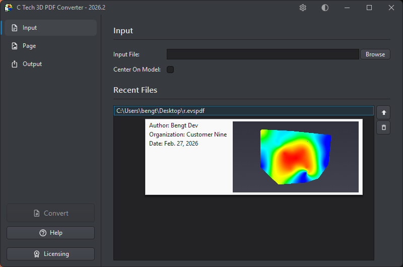
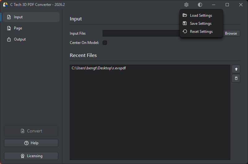
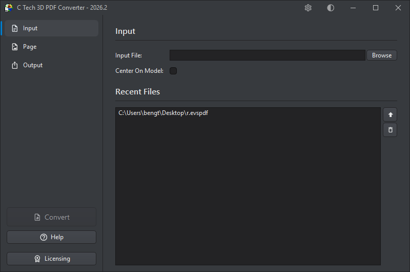
The Input section is where you select the source file for your 3D PDF.
Input File
Enter the path to an .evspdf file, or click Browse to select one. You can also drag and drop the file onto the input field.
Center On Model
When checked, the converter repositions the scene so the model is centered at the coordinate origin. This is recommended for models located far from the origin, which can display incorrectly in the PDF viewer with symptoms like jittery rotations and flickering surfaces. Centering the model eliminates these problems. Reported coordinates will still reflect the original model position.
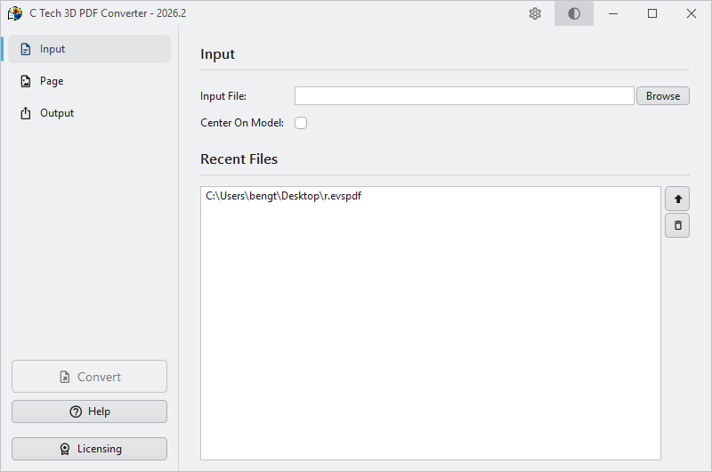
Recent Files
The Recent Files list shows up to 15 previously used EVSPDF files, making it easy to switch between projects. Double-click any entry to select it as the current input, or use the buttons on the right:
Button
Action
Use
Set the selected file as the current input
Remove
Remove the file from the recent list
File Preview
Hovering over any file in the Recent Files list shows a tooltip with metadata and a preview image of the model.
The following information is shown where available:
Field
Description
Author
The person who created the file
Organization
The organization or company
Date
The date the file was created
Project
The project name (hidden if not set)
Description
A description of the contents (hidden if not set)
Restrictions
Any usage restrictions (hidden if not set)
Preview
A thumbnail image of the 3D model
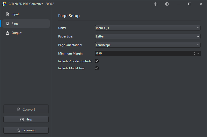
The Page section controls the dimensions and layout of the output PDF page, as well as optional controls embedded in the PDF.
Units
Choose the measurement units for page dimensions and margins. Changing the units will automatically convert the existing margin value so nothing is lost. This setting also controls the units used for measurements performed in the embedded 3D view of the generated PDF.
Unit
Abbreviation
Millimeters
mm
Inches
"
Points
pts
Pixels
px
Paper Size
Select a standard paper size from the dropdown. Available options include:
Category
Sizes
US
Letter, Legal, Executive, Folio, Ledger, Tabloid
ISO A-series
A0 – A10
ISO B-series
B0 – B10
ISO C-series
C0 – C10
Page Orientation
Choose between Landscape (wider than tall) and Portrait (taller than wide) to match the intended layout of your document.
Minimum Margin
Sets the minimum margin around the 3D content area, in the selected units. The default is 0.70 inches. When you change the units, the margin value is automatically converted so the physical size remains the same.
The dropdown arrow button on the right side of the field opens a built-in calculator, letting you enter an expression (such as 25.4 / 2) that is evaluated and applied as the new margin value.
The actual margins depend on how the aspect ratio of the poster image (the static preview of the 3D scene) compares to the chosen page size:
If the aspect ratio of the poster image precisely matches the chosen page size, all margins will be equal and set to the Minimum Margin.
If the aspect ratio of the poster image is more landscape than the chosen page size, the left and right margins will equal the Minimum Margin and the top and bottom margins will be larger.
If the aspect ratio of the poster image is more portrait than the chosen page size, the top and bottom margins will equal the Minimum Margin and the left and right margins will be larger.
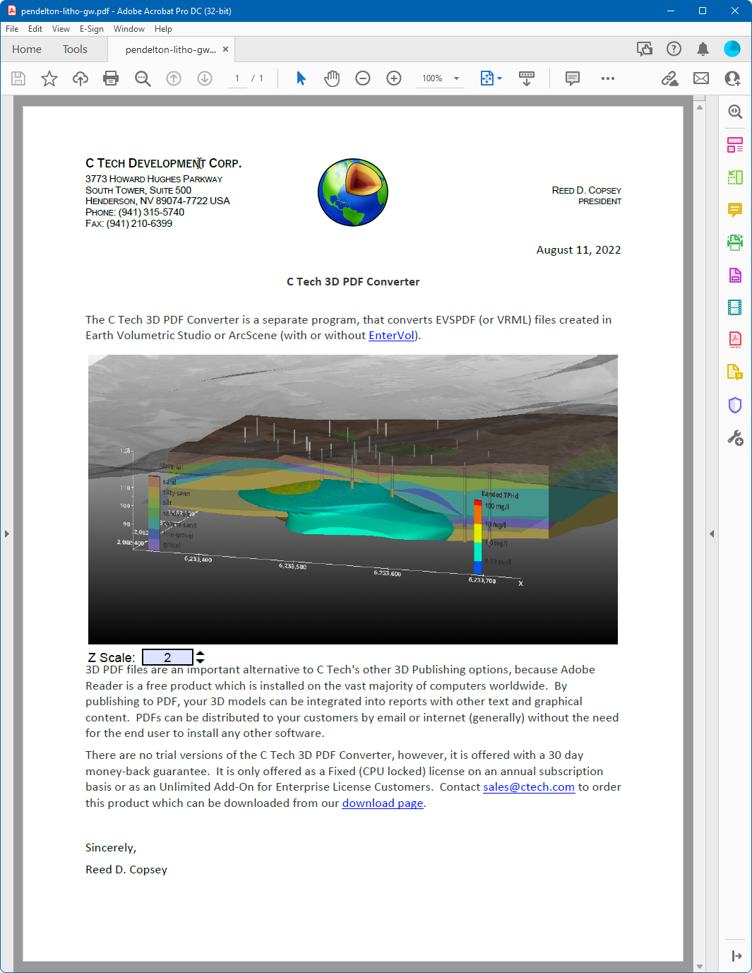
Include Z Scale Controls
When checked, the generated PDF includes vertical exaggeration controls that let the viewer adjust the Z scale interactively while viewing the model.
Include Model Tree
When checked, the generated PDF includes a model tree panel that allows the viewer to toggle the visibility of individual parts of the 3D model. This is particularly useful for complex models with multiple named components.
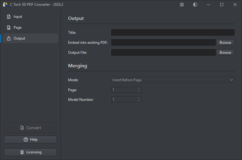
The Output section is where you specify where the generated PDF will be saved, and optionally how it should be merged into an existing PDF document.
Title
An optional title for the PDF document. The title also appears as the root node name in the Model Tree. Titles should be less than 30 characters — if left blank, the title will default to “EVS Scene”.
Embed into Existing PDF
If you want to merge the 3D content into an existing PDF rather than creating a new standalone file, enter the path to the target PDF here, click Browse, or drag and drop a PDF onto the field. Once a template PDF is selected, the Merging options below will become available.
To prepare a template PDF with placeholder 3D annotations that can be replaced with converted models, see Creating Template PDF Files.
For a walkthrough of the full process — from setting up a template to replacing placeholders with 3D content — see Using Template PDF Files.
Tip
Alternatively, you can output a PRC file from the converter and use Adobe Acrobat Pro to insert it into an existing PDF manually. See Using Adobe Acrobat with PRC Files for details.
Output File
Specifies where the generated PDF will be saved. Click Browse to choose a location, or type the path directly. The output file can be set to the same path as the Embed into Existing PDF field — in that case, the converter will read the existing PDF, merge in the 3D content, and write the result back to the same file, effectively updating it in place.
Info
You can also save the output as a .prc file instead of a PDF by changing the file extension. PRC files can be inserted directly into existing PDFs using Adobe Acrobat Pro — see Using Adobe Acrobat with PRC Files for instructions.
Merging
These options control how the 3D content is inserted into the template PDF, and are only available when a template has been specified above.
Mode — Determines how the 3D content is placed within the template:
Mode
Description
Insert Before Page
Inserts the 3D content as a new page before the specified page number
Insert After Page
Inserts the 3D content as a new page after the specified page number
Replace 3D Model
Replaces an existing 3D annotation in the template PDF. This is covered in detail in the Using Template PDF Files topic.
Page — The page number in the template PDF used as the reference point for insertion (for Insert Before/After modes).
Model Number — When using Replace 3D Model mode, this identifies which 3D annotation on the specified page should be replaced, for pages that contain multiple 3D models. Minimum value: 1.
Info
You can only replace or insert one 3D model at a time. For multiple models, perform sequential operations — use the output file from each operation as the input for the next.
Subsections of Output
If you want to embed a 3D model within a page of an existing PDF report (rather than inserting it as a full page), you first need to place a placeholder 3D object in the document using Adobe Acrobat Pro. The C Tech 3D PDF Converter can then replace that placeholder with your actual 3D content.
Info
If you want to insert a full-page 3D PDF into an existing document, no placeholder is needed. Use the Insert Before Page, Insert After Page, or Replace 3D Model options in the Output section.
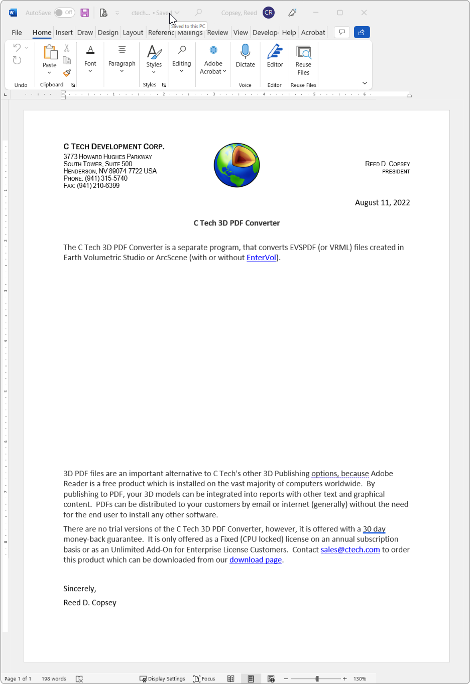
Step 1 — Prepare the Document
In your authoring application (such as Microsoft Word), leave a blank space on the page where the 3D model should appear:
Export or save the document as a PDF in the usual way.
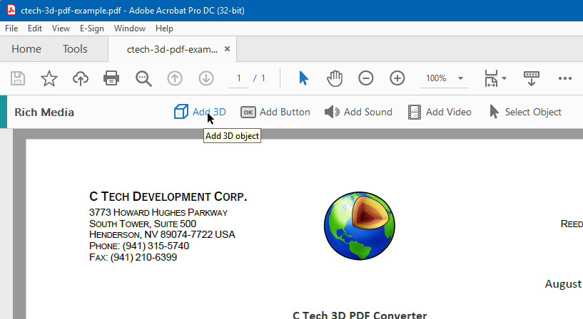
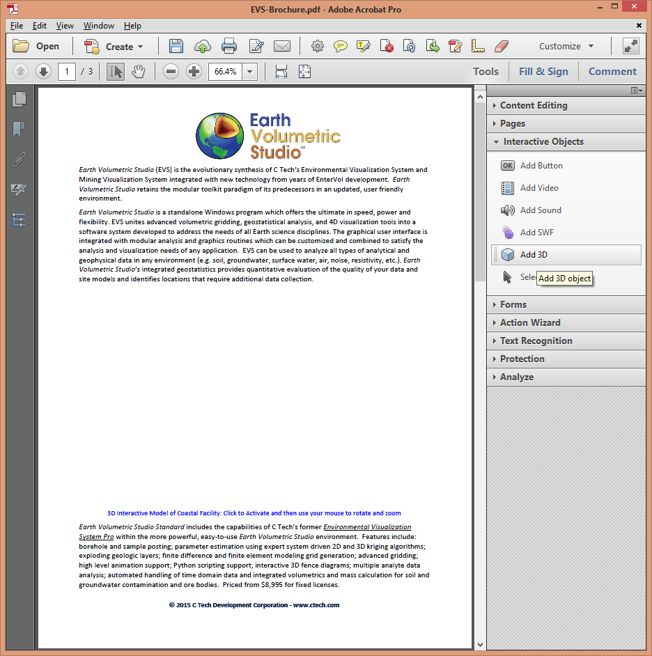
Step 2 — Insert the Placeholder in Adobe Acrobat Pro
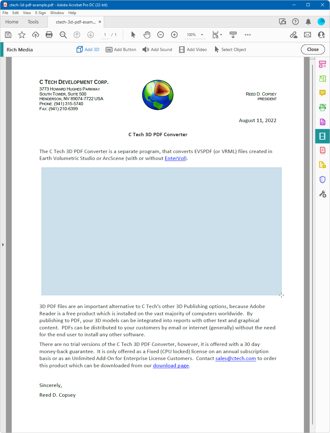
Open the PDF in Adobe Acrobat Pro DC and go to Tools > Rich Media > Add 3D:
Draw a rectangle over the blank area where the 3D model should be placed:
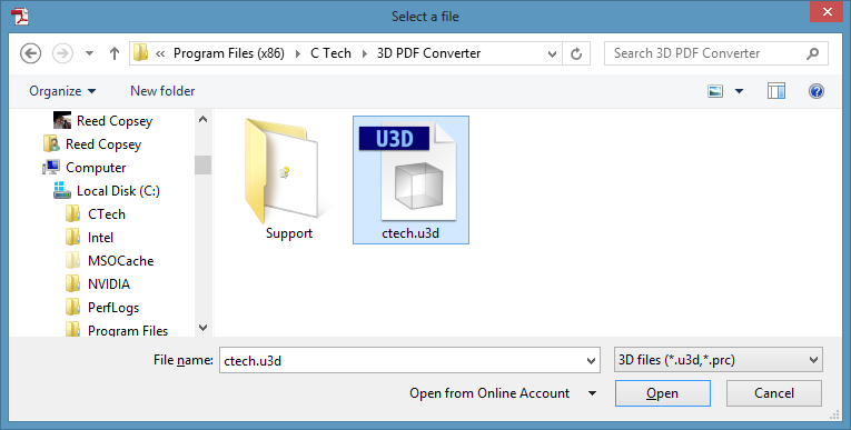
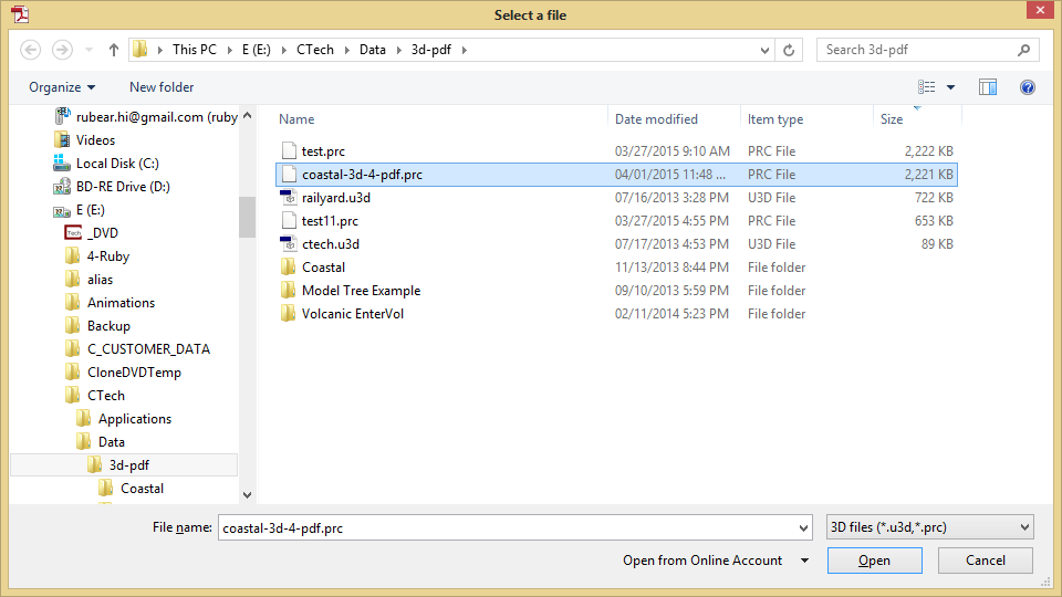
When prompted for a file, click Browse and select ctech.u3d:
This inserts the placeholder 3D object into the document:
Repeat this process for each additional 3D model you need in the document, then save the PDF.
The Replace 3D Model mode in the C Tech 3D PDF Converter lets you substitute an existing 3D annotation in a PDF with your own 3D content. This is how you update a document that already has a placeholder or an older 3D model embedded in it.
To use this mode, you need a PDF that already contains one or more 3D models or placeholders. A sample PDF with C Tech logo placeholders is included with the installer. For instructions on creating your own template, see Creating Template PDF Files.
Replacing the Annotation
To replace a 3D model, you only need to know which page it is on and which annotation number it is on that page. Open the C Tech 3D PDF Converter and configure the Output section as follows:
Set Embed into Existing PDF to the PDF containing the placeholder
Set Mode to Replace 3D Model
Set Page to the page number containing the 3D annotation
Set Model Number to the annotation number on that page (use 1 if there is only one)
The new 3D content will automatically fill the size and position of the existing annotation.
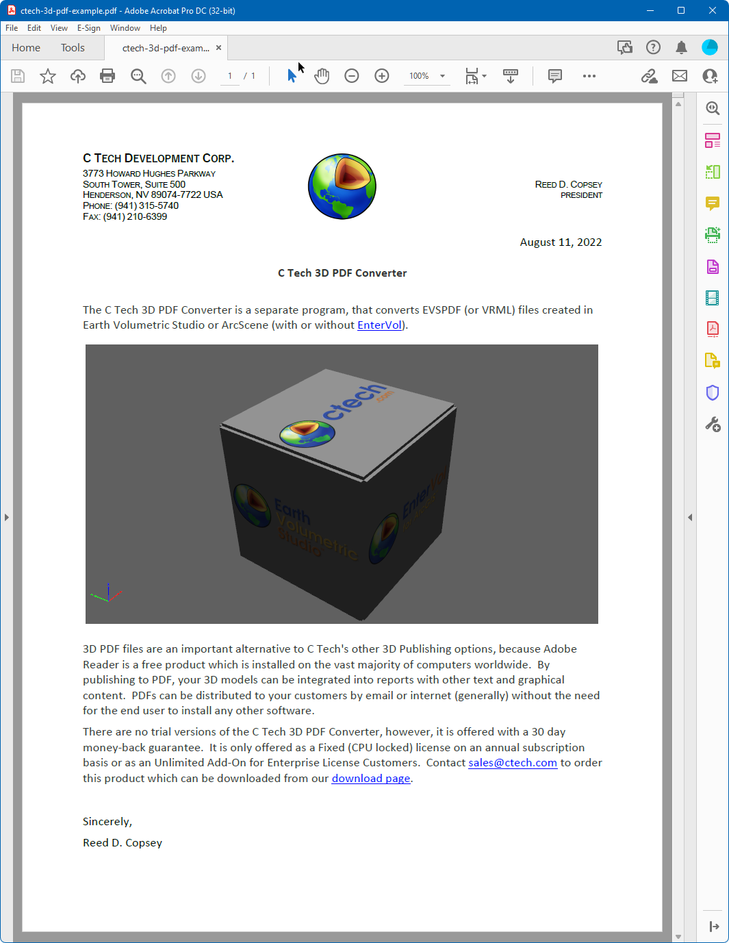
After converting, the placeholder is replaced with your 3D content:
The C Tech 3D PDF Converter can output both PDF and PRC formats. While PDF files can be viewed immediately as interactive 3D documents, PRC files must be inserted into an existing PDF using Adobe Acrobat Pro. This approach is useful when you want to place a 3D model within a specific area of a page in an existing report.
Info
PRC files do not include the lighting and rendering information that is embedded in 3D PDFs. If the visual quality of PRC output is not acceptable, use the PDF output format instead.
Inserting the PRC File
In your authoring application, leave a blank space on the page where the 3D model should appear, then export the document as a PDF. Open the PDF in Adobe Acrobat Pro:
Go to Tools > Rich Media > Add 3D, then draw a rectangle over the area where the 3D model should be placed. When prompted for a file, click Browse and select your PRC file:
Result
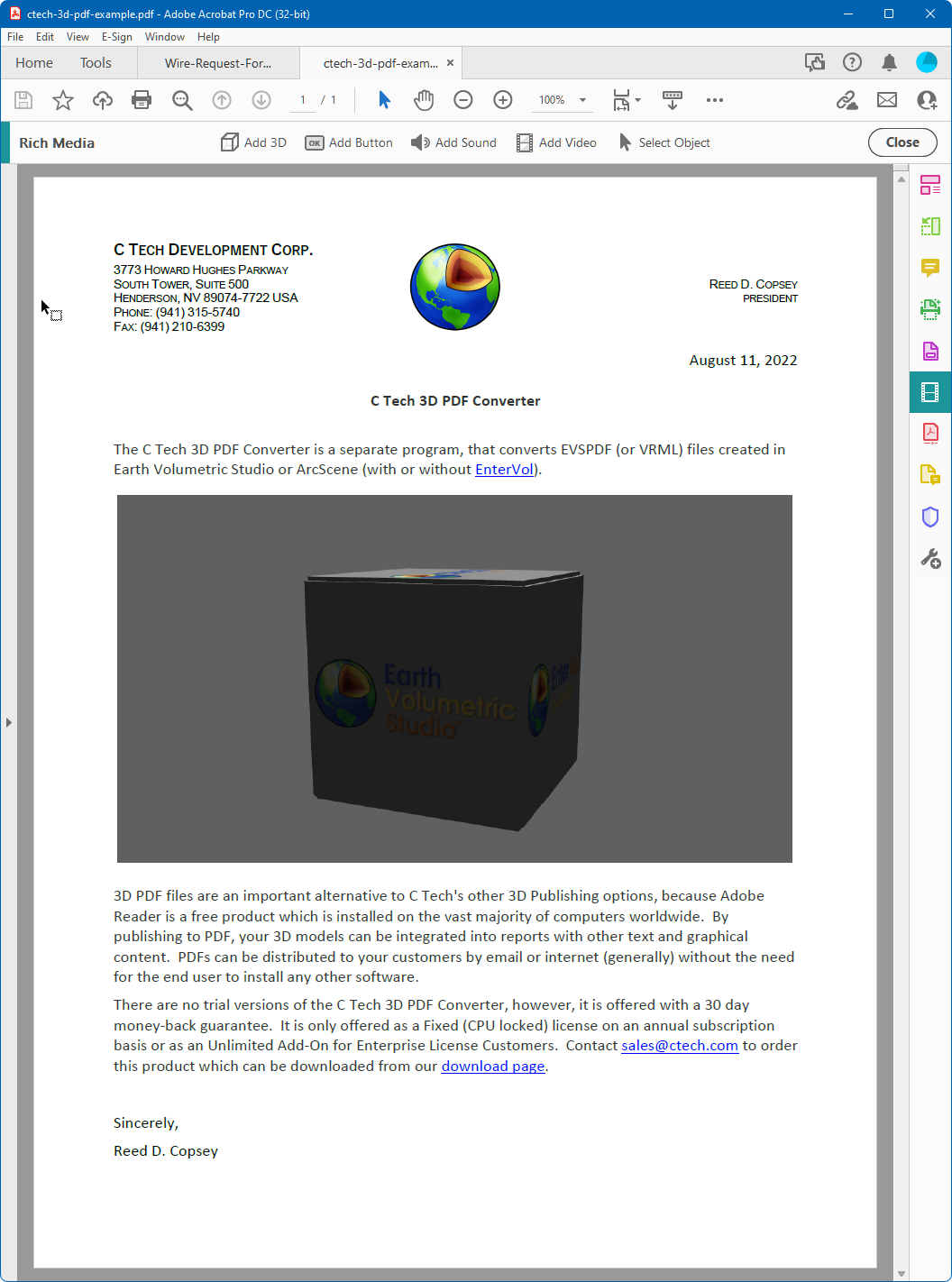
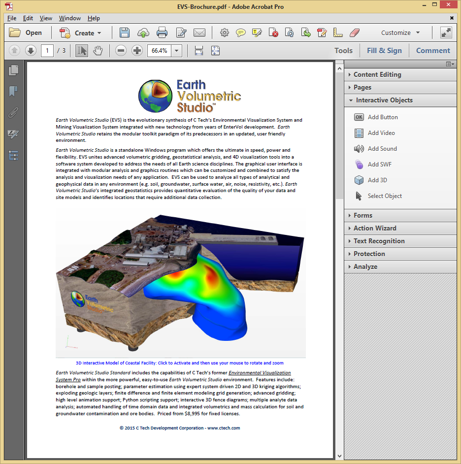
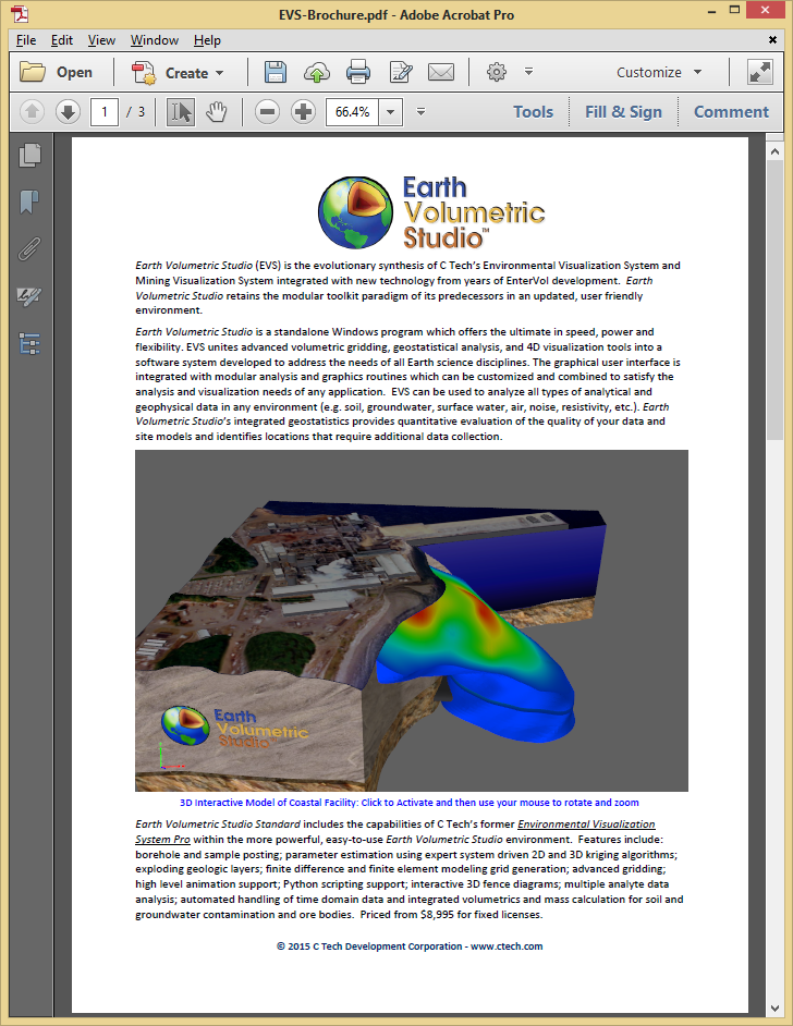
When the document is first opened, the poster image is displayed in place of the 3D model:
Clicking on the image activates the interactive 3D content:
Converter settings are managed through the gear icon in the title bar. Clicking it opens a small flyout menu with three options:
Option
Description
Load Settings
Load a previously saved settings file, restoring all options to the state they were in when saved
Save Settings
Save all current settings to a file so they can be reloaded later — useful when working with multiple projects or configurations
Reset Settings
Reset all settings back to their defaults
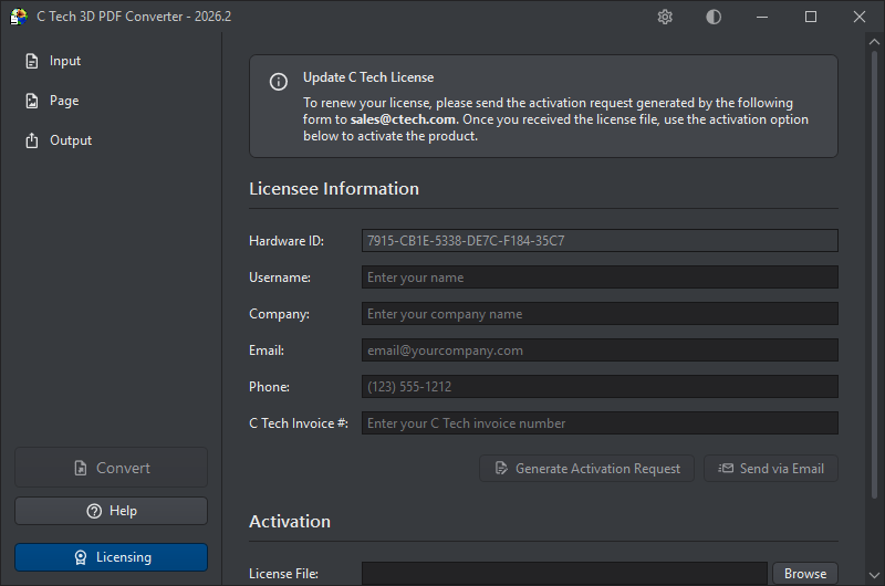
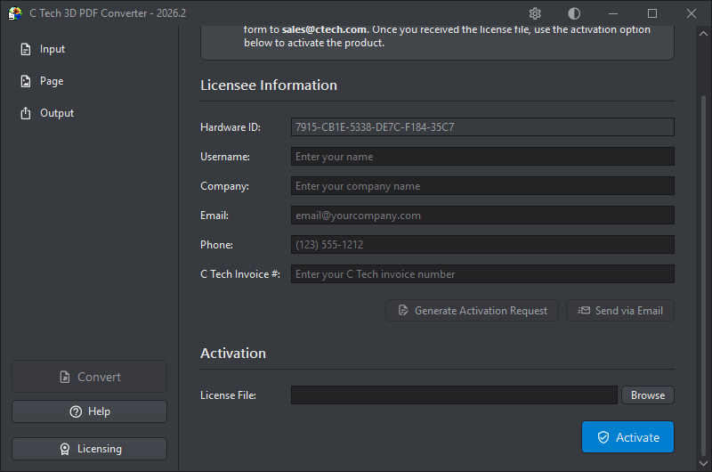
The Licensing button at the bottom of the sidebar opens the licensing dialog, where you can activate a new license or renew an existing one.
The dialog is split into two parts. Scroll up to see the Licensee Information and activation request controls:
Scroll down to reach the Activation section, where you load your license file and activate:
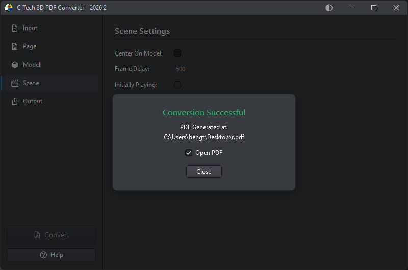
Once you have configured your settings, click Convert at the bottom of the sidebar to begin. When conversion completes successfully, a confirmation dialog is shown with the path to the generated PDF.
The Open PDF checkbox, which is checked by default, will open the generated PDF in your default PDF viewer as soon as you click Close. Uncheck it if you want to close the dialog without opening the file.
If the conversion fails, an error log is shown in place of the success dialog, describing what went wrong.
The converter supports light and dark themes, toggled by the circle button in the title bar. In the light theme, the button shows a moon icon — click it to switch to dark. In the dark theme, it shows a sun icon — click it to switch back to light.
All C Tech products with theme support — including Earth Volumetric Studio and the C Tech License Manager — share the same theme configuration. Switching the theme in any of these applications will cause all others to match that theme on their next startup.